October 15, 2026
Heavy Plate Rolling and Advanced Welding: Engineering Capabilities for Large Pressure Vessels
1. Introduction
I've been involved in pressure vessel fabrication and supplier evaluation for close to two decades. Started in a weld shop, spent years in QA/QC on nuclear components, and for the last several years I've been helping EPC contractors and plant owners assess whether a fabricator can actually build what they're quoting.
And I can tell you this: when you move past the commodity range — vessels under 38mm wall thickness, standard carbon steel, moderate diameters — the supplier pool shrinks dramatically. Not because fabricators don't want the work, but because two capabilities become non-negotiable gatekeepers: heavy plate rolling and advanced welding.
Heavy plate rolling determines whether a shop can form the shell in-house or has to subcontract it to a specialist roller. Advanced welding — specifically narrow gap SAW, automated systems, and properly controlled heat input — determines whether the thick-wall seams can be completed efficiently, with the required mechanical properties, and without a defect rate that turns the project into a rework exercise.
The global heavy pressure vessel market was estimated at US$45.5 billion in 2025 and is projected to reach US$78.4 billion by 2032, growing at a CAGR of 8.2%. The steel pressure vessel and tank segment, valued at US$52.2 billion in 2025, is expected to reach US$65.4 billion by 2034 at a 3.4% CAGR, with petrochemical and oil & gas accounting for over 50% of consumption. Petrochemical demand — reactors, separators, and storage vessels for plastics, fertilizers, and specialty chemicals — is valued at over US$4 trillion annually, and the demand for high-pressure, corrosion-resistant systems keeps increasing.
Here's what the market data tells you about sourcing: customers almost never switch vessel fabricators mid-project. The switching costs are extreme because of ASME certification requirements, project-specific engineering, and the sheer length of the qualification process. That means the evaluation you do before the first purchase order is the most consequential decision in the entire procurement cycle.
This guide breaks down the engineering capabilities that separate a fabricator who can build large thick-wall pressure vessels from one who can only quote them — the rolling equipment, the welding processes, the heat treatment, the inspection, and the verification framework I use when assessing suppliers.
2. Why These Two Capabilities Define the Supplier Pool
Before diving into the technical details, let me explain why rolling and welding — specifically — are the gatekeepers.
A pressure vessel is essentially a rolled cylinder with welded seams, dished heads, and nozzle attachments. The shell is formed by rolling plate into a cylinder and welding the longitudinal seam. Multiple shell courses are joined with circumferential seams. Heads are formed separately and welded to the shell ends. Nozzles are welded into the shell wall.
Every one of those steps depends on rolling and welding capability. A shop that can't roll heavy plate in-house either outsources the forming (losing control over tolerances and schedule) or limits its vessel size to what its equipment can handle. A shop that can't execute thick-wall welding efficiently either loses money on every project or produces welds that fail inspection.
The labor reality makes this even more acute. The American Welding Society projects a shortage of 360,000 welders by 2027, with more than 157,000 welders nearing retirement. For fabricators working under ASME code requirements, that labor gap compounds the challenge of maintaining quality while meeting regulatory standards. Shops that have invested in automation and advanced processes can maintain capacity despite the labor shortage. Shops that haven't are competing for a shrinking pool of skilled welders.
The demand profile also favors capable suppliers. Value growth in the pressure vessel market is being led by high-alloy stainless steel and clad vessels for corrosive and high-purity services. The competition is engineering and certification-led, not price-led. Suppliers with ASME Section VIII certification, heavy fabrication expertise, and advanced welding technologies are the ones capturing the high-value work.
3. Heavy Plate Rolling: Equipment, Capacity, and the Thickness Threshold
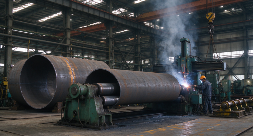
Plate rolling is the first capability that separates the supplier pool. The equipment determines the maximum thickness, the maximum diameter, and the achievable roundness and weld fit-up.
The Equipment Types
Three-roll machines are the traditional workhorse. The plate is bent between three rolls — a top roll and two bottom rolls. They're simpler and less expensive than four-roll machines, but they require the plate to be pre-bent separately to eliminate flat sections at the ends.
Four-roll machines have become the standard for heavy pressure vessel work. The additional roll provides better control over the bending process, eliminates the need for separate pre-bending, and achieves tighter roundness and seam fit-up. The four-roll configuration is widely described as a perfect rolling solution for the construction of pressure vessel shells. Modern four-roll machines use hydraulic and mechanical symmetry — exerting equal force across the rolls — to ensure uniform load distribution along the plate width, minimizing distortion and maintaining tight tolerances.
The key equipment specification that matters for sourcing is the maximum plate thickness at the maximum rolling width. A machine rated for 4 inches (100mm) at a narrow width may only handle 2 inches (50mm) at full width. The capacity varies with the material yield strength — rolling 100mm of SA-516 Gr 70 is more demanding than rolling 100mm of mild steel.
TransTech Fabrication, for example, installed a new heavy-duty plate roller in 2025 with the capacity to roll plate up to 4 inches thick. That capacity translates directly to fabrication capability: it allows the shop to produce heavy-wall vessel and shell components in-house, without outsourcing or sub-contracting this critical step. The in-house control means tighter tolerances, faster cycle times, and one fewer external dependency in the project schedule.
At the extreme end, variable-geometry configurations allow rolling of plates up to 12 inches thick. But those machines are rare, and the shops that operate them are a very short list.
The Capacity Question
When evaluating a fabricator, ask for three numbers: maximum plate thickness, maximum rolling width, and maximum diameter. Then ask for the thickness at the full width — because that's the number that determines what they can actually produce without compromising tolerance.
A shop that can roll 100mm plate at a 2-meter width but only 50mm at 4 meters has a different capability profile than one that can hold 80mm at full width. The vessel diameter and shell length you need determine which machine the shop will use, and therefore which thickness limit applies.
The vertical configuration option also matters for large-diameter work. When rolling heavy plates horizontally, gravity causes the plate to sag during the bending process, which affects roundness and fit-up. Vertical rolling configurations address this by leveraging gravity naturally throughout the bending process, maintaining roundness and preventing plate sagging. For vessels over 4 meters in diameter, the vertical configuration is often the difference between achieving the required roundness and fighting the process.
4. Roll Deflection and the Geometry Problem Nobody Talks About
Here's a technical detail that separates the good fabricators from the excellent ones: how they manage roll deflection under load.
When rolling heavy plates into thick cylindrical shells, the immense forces required naturally cause the machine frame and the rolls to deflect under load. If that structural deflection isn't precisely managed, it introduces geometric errors — extended flat sections at the plate ends and a barrel effect on the cylinder body.
The barrel effect is exactly what it sounds like. The center of the plate deflects more than the edges because the bending moment is highest at the center. The result is a cylinder that's larger in the middle than at the ends. When the longitudinal seam is welded and the cylinder is checked for roundness, the center bulges outward. The weld fit-up at the seam is compromised because the edges don't come together properly.
Crowning compensation is the solution. This uses a calculated roll profile — the rolls are machined with a slight crown (a larger diameter in the center than at the ends) that offsets the deflection under load. The result is even pressure across the full plate width and a clean cylinder without barrel shapes or flat sections.
For a 100mm thick plate rolled to a 3-meter diameter, the uncorrected deflection at the center can be 2–5mm. With crowning compensation, it's held within 0.5mm. That difference determines whether the longitudinal seam gap is within the tolerance required for a quality weld.
What to Verify
Ask the fabricator about their roll crowning system. A shop that uses a hydraulic crowning system with calculated roll profiles is one that has engineered the deflection problem. A shop that doesn't mention it may not have addressed it.
Also ask about their pre-bending procedure. Four-roll machines with proper control can perform pre-bending in the same setup as the main rolling. Three-roll machines require a separate pre-bending step, which introduces the risk of flat sections if the operation isn't carefully controlled.
The differential temperature rolling technique is another approach worth knowing about. Research on Q345R steel plates for pressure vessels found that differential temperature rolling effectively suppresses head warping induced by asymmetrical rolling, achieving an 85.67% reduction in maximum curvature. This technique isn't universal, but it demonstrates the level of process sophistication that leading fabricators are bringing to the rolling operation.
The Roundness Tolerance
For pressure vessel shells, cylindricity and out-of-roundness tolerances are typically held within 1% of the nominal diameter. For a 3-meter diameter shell, that's 30mm of allowable ovality. That sounds generous, but it's not — the out-of-roundness directly affects weld fit-up, and poor fit-up requires either excessive root gaps (which increase the risk of burn-through) or forced alignment (which introduces residual stresses).
For shells over 4 meters in diameter, out-of-roundness control becomes more difficult because the plate stiffness decreases relative to the diameter. Heavy internal bracing before welding is often required to maintain roundness through the welding operation.
5. Narrow Gap SAW: The Process That Changed Thick-Wall Economics
Submerged arc welding (SAW) has been the standard for thick-wall pressure vessel seams for decades. The process delivers deposition rates of 10–25 kg/h, zero spatter, and deep penetration — characteristics that make it mandatory for shell seams above 38mm.
The economics of SAW on thick plate come down to one thing: the number of passes required to fill the joint. A conventional V-groove joint on a 100mm wall requires a large groove volume that must be filled layer by layer, pass by pass. Every pass costs arc time, filler material, and energy. Narrow gap SAW changes that equation by reducing the groove volume.
How Narrow Gap SAW Works
Instead of a wide V-groove, narrow gap SAW uses a deep, narrow groove — typically 8–18mm wide with a groove angle of 1–3 degrees. A special torch with a long, slender nozzle reaches deep into the narrow groove to deposit the weld metal at the bottom.
The process uses a two-beads-per-layer sequence, with the SAW torch oscillating slightly to place one bead on each side of the groove. The narrow groove means less filler metal is required, fewer passes are needed, and the heat input per pass is more precisely controlled.
The efficiency gain is substantial. In a documented case study, switching from a standard V-bevel SMAW/GMAW process to narrow gap SAW on an 80mm pipeline reduced total arc-time by 6–7 minutes per layer while refining the HAZ grain structure to Level 7. For a 100mm wall with 30+ layers, that's hours of arc time saved per seam.
The filler metal saving alone is significant. Narrow gap preparation provides a 35% filler material saving compared to conventional V-groove preparation. On a large vessel with multiple longitudinal and circumferential seams, that saving directly reduces material cost.
The Double-Wire Innovation
The most significant advancement in narrow gap SAW for pressure vessel applications is the double-wire (tandem) configuration. A research team in China developed a double-wire narrow gap SAW process specifically for thick-walled low-alloy steel pressure shells in fourth-generation nuclear high-temperature gas-cooled reactor steam generators.
The configuration uses a tandem dual-wire single-pool setup. The leading wire operates with direct current electrode positive (DCEP) at 500–650 A to ensure penetration depth. The trailing wire operates with alternating current electrode positive (ACEP) at 470–600 A to expand the weld width.
The result: a welding speed of 500–600 mm/min and a 1.5–2× efficiency improvement over single-wire SAW. Joint tensile strengths of 690–720 MPa, a mean heat-affected zone impact energy of 127.7 J at -20°C, and a 100% qualification rate on non-destructive testing. The technology was successfully applied to ⌀3866 mm × 95 mm steam generator shell circumferential welds, achieving full-position automatic welding with defect-free fusion and no undercut or porosity.
The dedicated welding wire and flux developed for this process — H15Mn2NiMoHR wire with SJ16HR alkaline flux — demonstrated a mean Charpy impact energy of 161.7 J at -20°C for deposited metal, with sulfur and phosphorus controlled to 0.0013% and 0.0030% respectively. That's the level of consumable control required for nuclear-grade thick-wall welding.
When Narrow Gap SAW Is Appropriate
Narrow gap SAW is feasible for plate thicknesses exceeding 50mm, with gap widths up to 16mm and electrode diameters of 2–5mm. For thicknesses below 50mm, the conventional V-groove SAW is usually more economical because the setup time for the narrow gap torch isn't justified.
For thicknesses above 100mm, narrow gap SAW becomes essential. The groove volume in a conventional V-groove at 150mm thickness is enormous, and the number of passes required would make the welding operation impractical.
6. Welding Automation: Robots, Cobots, and the Labor Reality
The welding labor shortage is driving automation adoption across the pressure vessel industry, but the approach varies depending on the production profile.
Flexible Welding Cells for Large Vessels
The Fedegari Group case, which I'll discuss in detail later, demonstrates what large-scale automation looks like. The company installed two flexible welding cells based on ABB gantry-mounted robots, with handling equipment that allows loading one vessel while the robot works on another. The offline programming system — RobotStudio — means the next job can be prepared while the current one is in progress, avoiding unnecessary downtime.
This approach reduced the time to produce specialized autoclave pressure vessels for the pharmaceutical industry by 50 percent. The key was not speeding up the welding itself — international standards prevent alterations to welding speed or voltage — but improving the overall efficiency of the production process.
Cobots for High-Mix, Low-Volume Fabrication
For fabricators with a high-mix, low-volume product profile, collaborative robots (cobots) offer a different value proposition. Cobots integrate force-torque sensors that detect contact and stop movement, removing the need for safety cages and dedicated floor space.
The programming method is the key difference. Most cobot systems enable operators to physically guide the robotic arm through the desired weld path and record the motion for future cycles. This hand-teaching method takes about 10 minutes for simple applications, compared to weeks of offline programming typical for traditional robotic cells.
The cost difference is also significant: complete cobot welding systems run $95,000 to $140,000, while traditional robotic cells start around $200,000 and often push past $300,000.
Performance parameters for cobots on pressure vessel work show 20–30 inches per minute on structural carbon steel, reaching 90 inches per minute on thin-gauge materials where heat input control prevents distortion. Multi-pass welds on ASME Section VIII pressure vessels require precise inter-pass positioning, which cobots deliver through programmable torch angle adjustments.
The Quality Improvement
The A.O. Smith case illustrates the quality impact of automation. Their Ashland City facility completes one tank every 45 seconds across 1.5 million units annually. Their shift from hard automation to flexible robotic welding brought leak detection failures down from roughly 10 percent to near-zero.
That's the operational argument for automation: not just labor savings, but quality consistency that manual welding can't match. A robot performs the same motion with the same parameters on every pass. A human welder's parameters drift with fatigue, distraction, and the simple fact that no two passes are identical.
7. Post-Weld Heat Treatment: The Step That Determines Whether the Weld Survives
Thick-wall welding generates residual stresses that can lead to cracking, distortion, and premature failure. Post-weld heat treatment (PWHT) relieves those stresses by heating the vessel to a temperature below the lower critical temperature and holding it long enough for the stresses to relax.
For thick-wall vessels, PWHT isn't optional — it's mandatory under ASME Section VIII and EN 13445. The specific requirements depend on the material and thickness. ASME Section VIII Division 1 requires PWHT for carbon steel above certain thickness thresholds, and the holding temperature and time are specified in the code tables.
The Heated Band Width
For local PWHT on large vessels, the heated band width is critical. Research on 60–70mm thick cylinder butt welds found that the heated band width should be not less than six times the thickness. For a 100mm wall, that's a 600mm band on each side of the weld. If the heated band is too narrow, the stress relief isn't uniform, and new stresses can be introduced at the transition zone.
For ultra-large pressure vessels, researchers have developed stress regulation theories that use primary plus secondary heating zones to induce compressive stress on the inner surface of the vessel. This is more sophisticated than simple stress relief — it's active stress engineering that improves the fatigue life of the vessel.
The Tempering Interaction
One critical process detail: for quenched and tempered steels, the PWHT temperature must be below the original tempering temperature. If the PWHT temperature exceeds the tempering temperature, it can over-temper the base metal and reduce its strength.
Research on 194mm thick SA-516 Grade 70 plates found that tempering temperatures exceeding PWHT temperatures increase the risk of embrittlement. The PWHT schedule has to be designed around the material's original heat treatment, not applied generically.
What to Verify
Ask the fabricator for their PWHT procedure for your specific material and thickness. The procedure should specify the heating rate, holding temperature, holding time, and cooling rate. For local PWHT, it should specify the heated band width and the method of temperature control.
The furnace calibration records are also important. A digitally-controlled heat treatment furnace with documented temperature uniformity is the baseline for quality PWHT. A shop that does PWHT in a makeshift furnace without calibrated temperature control is a shop that's guessing at the stress relief.
8. Inspection: Phased Array UT and the Limits of Radiography
The inspection method for thick-wall welds determines whether defects are found before the vessel ships or after it fails.
The Radiography Limitation
Radiographic testing (RT) has been the traditional method for weld inspection, but it has a fundamental limitation for thick-wall welds: the thicker the wall, the less effective RT becomes. For wall thicknesses above 100mm, radiography is described as a significant challenge. The X-ray or gamma-ray source has to penetrate through the full thickness, and the contrast between a defect and the surrounding material decreases with thickness.
Phased Array UT
Phased array ultrasonic testing (PAUT) has emerged as the preferred method for thick-wall weld inspection. PAUT uses a multi-element probe that electronically steers and focuses the ultrasonic beam, allowing inspection of complex geometries and thick sections with better defect detection and sizing accuracy than conventional UT.
For a 150mm thick pressure vessel with an insert nozzle, phased array ultrasonic testing was used as a substitute for radiographic testing, overcoming the challenges that RT couldn't address. For reactor pressure vessel thick-wall cylinder welds, phased array testing technology achieved detection capability and quantitative accuracy that meet ASME code qualification requirements.
The advanced ultrasonic testing (AUT) system approach is another option. Zhongneng Huajian installed a state-of-the-art automated ultrasonic testing system specifically to ensure weld integrity in the thicker sections of super-sized vessels, providing quality assurance and documentation for critical applications.
Time of Flight Diffraction (TOFD)
TOFD is another ultrasonic technique that's particularly well-suited for heavy wall thickness welds. Unlike conventional UT, which relies on amplitude-based detection, TOFD measures the time of flight of diffracted signals from the tips of defects. This provides accurate sizing of defects and is less sensitive to the orientation of the defect relative to the beam.
What to Verify
Ask the fabricator what NDT methods they use for thick-wall welds. For walls above 50mm, phased array UT or TOFD should be the primary method. For critical applications, ask for the probability of detection (POD) data for the specific technique and defect types.
The NDT personnel certification is also important. ASNT Level II or Level III certification for the specific technique is the baseline. A shop that uses uncertified personnel for thick-wall inspection is a shop that's hoping you won't ask about the certification records.
9. Real-World Case: Fedegari Group's 50% Reduction in Autoclave Production Time
Let me share a case that illustrates how advanced welding automation transforms production capability.
The Challenge: Fedegari Group, an Italian manufacturer of pharmaceutical autoclave pressure vessels, was facing growing demand from pharmaceutical manufacturers. The company produces customized welded pressure vessels for autoclave manufacturers, meaning very few of the pressure vessels are the same, requiring a highly flexible production system that can produce precision joints and handle widely varying sizes and geometry.
The welding parameters were fixed by international standards, so the company couldn't achieve speed improvements by altering the welding head speed or voltage. The efficiency had to come from the production process itself.
The Solution: ABB supplied two flexible welding cells based on gantry-mounted robots, along with the RobotStudio offline programming tool. The cells can weld both inside and outside large autoclave vessels, with handling equipment that allows loading one vessel while the robot works on another. The offline programming means the next job can be prepared while the current one is in progress, avoiding unnecessary downtime.
The flexibility was critical. The process entails handling a combination of bent sheet metal, pressure cover and door frames, with both stainless steel and carbon steel being used. Three different welding materials are used, and the robot needs to change its welding torch up to three times depending on the product. Both interior and exterior welding operations needed to be performed without stopping to move the autoclaves.
The Result: The company reduced the time to produce specialized autoclave pressure vessels by 50 percent. The final cell design covered 83 percent of the various pressure vessel sizes in Fedegari's product range.
The Lesson: The efficiency gain didn't come from welding faster. It came from eliminating the downtime between jobs — the programming time, the setup time, the changeover time. The offline programming system allowed programs to be prepared while the welding cell was working on the current product, and the robot's flexibility meant it could handle the different materials and geometries without manual reconfiguration. For a high-mix, low-volume fabricator, that's the difference between profitable and unprofitable production.
10. What to Verify When Sourcing Large Pressure Vessels
Here's the framework I use when evaluating fabricators for heavy-wall pressure vessel projects.
Rolling Capability
Check | What to Request | Red Flag |
Maximum plate thickness | Thickness at full width and at narrow width | Only provides peak thickness |
Maximum rolling width | Width capability for heavy plate | Cannot specify width at thickness |
Roll crowning system | Hydraulic or mechanical crowning with calculated profile | No crowning compensation |
Pre-bending capability | In-line pre-bending (four-roll) or separate operation | No pre-bending documentation |
Roundness tolerance | Measured out-of-roundness on similar projects | Cannot provide measurement data |
Welding Capability
Check | What to Request | Red Flag |
SAW equipment | Number of stations, tandem/twin-wire capability | Single-wire only for thick wall |
Narrow gap SAW | Experience with narrow gap preparation and torch | No narrow gap experience |
Automated welding | Robot cells or cobot systems for repetitive seams | Manual welding only |
Welding procedure specifications | Qualified WPS for your material and thickness | Generic WPS without qualification |
Consumable control | Wire and flux certificates, hydrogen control procedures | No consumable traceability |
Heat Treatment and Inspection
Check | What to Request | Red Flag |
PWHT furnace | Calibrated furnace with documented temperature uniformity | No furnace calibration records |
PWHT procedure | Material-specific procedure with heating/cooling rates | Generic PWHT schedule |
Heated band width | Documented for local PWHT | No heated band calculation |
NDT capability | Phased array UT, TOFD, or AUT for thick wall | RT only for walls above 50mm |
NDT personnel | ASNT Level II/III certification for the technique | Uncertified inspectors |
Certification and Quality System
Check | What to Request | Red Flag |
ASME certification | Current ASME Section VIII Div. 1 or Div. 2 certificate | Expired or limited scope |
EN 13445 compliance | For European market projects | No EN certification |
Quality manual | Documented quality system covering all processes | Generic quality manual |
Traceability | Material heat lot traceability from mill to finished vessel | No traceability system |
11. Common Questions About Heavy Plate Rolling and Advanced Welding
Q: What's the maximum plate thickness that can be rolled for pressure vessel shells?
Variable-geometry plate rolling machines can handle plates up to 12 inches (305mm) thick. However, most fabricators have equipment rated for 4 inches (100mm) or less. The practical maximum depends on the machine capacity, the material yield strength, and the required diameter. For very thick plates, hot rolling or incremental forming may be required instead of cold rolling.
Q: When should narrow gap SAW be used instead of conventional SAW?
Narrow gap SAW is feasible for plate thicknesses exceeding 50mm. For thicknesses below 50mm, conventional V-groove SAW is usually more economical because the setup time for the narrow gap torch isn't justified. For thicknesses above 100mm, narrow gap SAW becomes essential due to the groove volume and the number of passes required with conventional preparation.
Q: How does narrow gap SAW reduce filler metal consumption?
Narrow gap preparation reduces the groove volume compared to a conventional V-groove. The groove is narrower (8–18mm vs. 30–60mm for a V-groove), which means less cross-sectional area to fill with weld metal. The 35% filler material saving is a documented figure for narrow gap SAW compared to conventional V-groove preparation.
Q: What's the heat input range for SAW on thick pressure vessel plate?
Heat input for SAW on thick plate varies with the process configuration and the material. For double-wire SAW with high heat input, the range can be 85–115 kJ/cm. For standard single-wire SAW, the heat input is typically lower, in the range of 20–50 kJ/cm. The key constraint is the balance between penetration (which requires higher heat input) and HAZ toughness (which benefits from lower heat input). The optimal heat input depends on the material and the required mechanical properties.
Q: Why is phased array UT preferred over radiography for thick-wall welds?
Radiography becomes less effective as wall thickness increases because the contrast between defects and the surrounding material decreases. For walls above 100mm, radiography is described as a significant challenge. Phased array UT provides better defect detection and sizing, allows inspection of complex geometries, and can be performed from one side of the weld.
Q: How long does post-weld heat treatment take for a thick-wall vessel?
PWHT duration depends on the material, the thickness, and the applicable code. For a 100mm thick vessel, the holding time might be 2–4 hours at temperature, with heating and cooling rates controlled to avoid thermal gradients. Including heat-up and cool-down, a full PWHT cycle for a large vessel can take 24–48 hours.
Q: Can a vessel be fabricated without PWHT if the wall is thin enough?
ASME Section VIII Division 1 specifies thickness thresholds below which PWHT isn't required for certain materials. For carbon steel, the threshold is typically around 38mm, depending on the material specification and the carbon equivalent. Above that threshold, PWHT is mandatory. EN 13445 has similar but not identical requirements.
12. Final Thoughts
Heavy plate rolling and advanced welding are the two capabilities that determine whether a fabricator can build large thick-wall pressure vessels or merely quote them. The equipment determines the maximum thickness and diameter. The welding process determines the efficiency, the quality, and the cost.
Here's what I'd tell any EPC contractor or plant owner evaluating fabricators for heavy-wall pressure vessel projects:
Verify the rolling capacity at the thickness you need. The maximum thickness rating is meaningless without knowing the width at that thickness. Ask for the thickness at full width and at the diameter you require. A shop that can roll 100mm at 2 meters but only 50mm at 4 meters has a different capability profile than one that can hold 80mm at full width.
Ask about roll crowning. The deflection of the rolls under load determines whether the cylinder is round or barrel-shaped. A shop with a calculated crowning compensation system is one that has engineered the problem. One that doesn't mention it may not have addressed it.
Narrow gap SAW is the standard for thick-wall seams. For walls above 50mm, narrow gap SAW reduces filler metal consumption by 35% and improves efficiency by 1.5–2× compared to conventional SAW. The double-wire configuration with DCEP lead and ACEP trail is the current state of the art for nuclear-grade applications.
Automation is about downtime, not welding speed. The Fedegari case showed that the 50% time reduction came from eliminating the downtime between jobs — the programming, the setup, the changeover. Offline programming and flexible cell design are what enable high-mix, low-volume fabricators to compete.
PWHT is material-specific. The post-weld heat treatment schedule has to be designed around the material's original heat treatment. A generic PWHT procedure that doesn't account for the tempering temperature can over-temper the base metal and reduce its strength.
Phased array UT is the inspection method for thick walls. For walls above 50mm, radiography becomes unreliable. Phased array UT or TOFD provides better defect detection and sizing. Ask for the POD data and the NDT personnel certification records.
The heavy pressure vessel market is heading toward US$78.4 billion by 2032, driven by petrochemical, LNG, and nuclear demand. The suppliers who will capture that growth are the ones who invested in heavy plate rolling capacity, narrow gap SAW, automated welding systems, and advanced NDT. The ones who didn't will keep quoting work they can't execute — and their customers will keep discovering the gap between the quotation and the finished vessel, usually after the first seam fails inspection.