June 26, 2026
Why Is Your Thin Film Evaporator Losing Vacuum? 5 Hidden Culprits
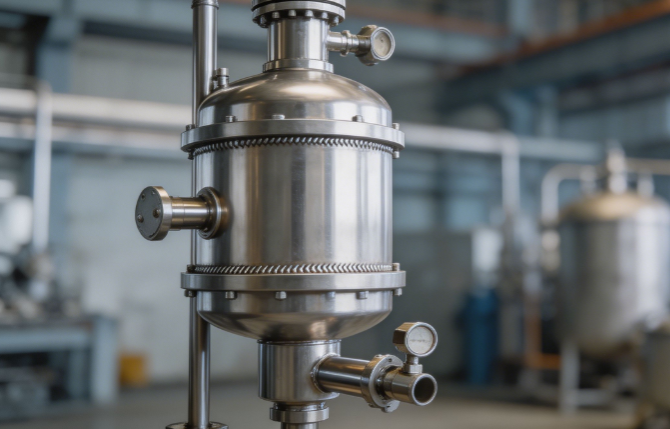
A thin film evaporator is a finely balanced system. It runs on a razor‘s edge between heat transfer, mass transfer, and vacuum. When the vacuum drifts, even by a few millibar, the entire evaporation curve shifts. The boiling point rises. The product overheats. The distillate quality drops. And the operator is left staring at a vacuum gauge that refuses to climb back to spec, cycling through the same three fixes that worked last time, none of which address what actually changed.
I’ve been called into enough troubleshooting calls to know that most vacuum problems in thin film evaporators are not caused by catastrophic failures. They are caused by slow, quiet changes that accumulate until the system can no longer compensate. Below are the five most common hidden causes, in the order they should be checked—because the first three are almost always overlooked while the operator chases the last two.
Table of Contents
Mechanical Seal Leakage: The Invisible Air Ingress
Condenser Fouling: When the Cold Side Stops Condensing
Dissolved Gases and Low Boilers: The Feedstream Surprise
Vacuum Pump Degradation: The Pump Is Not the Problem—Until It Is
Polymerization and Dead-Zone Outgassing: The Slow Burn
Troubleshooting Quick Reference
FAQ
Summary
Culprit 1: Mechanical Seal Leakage—The Invisible Air Ingress
The mechanical seal on the rotor shaft is the single most vulnerable point in the entire vacuum envelope. It is the only place where a moving part crosses the boundary between atmosphere and the high-vacuum process space. When the seal begins to leak, air enters the evaporator continuously, but at a rate so small that it rarely produces an audible hiss or a visible bubble. The vacuum pump works harder. The vacuum level slowly degrades.
The root cause is rarely the seal design itself. It is what the seal is exposed to. Process fluids that contain monomers, organic acids, or chlorinated solvents attack seal faces chemically. Thermal cycling—startup, shutdown, cleaning—creates micro-cracks in the seal faces through differential expansion. A seal that was rated for five years of continuous service can fail in twelve months if the process runs at the upper end of the temperature range.
Diagnosing a seal leak requires isolating the pump from the evaporator and performing a pressure-rise or vacuum decay test with the evaporator sealed. If the vacuum decays faster than the system's baseline leak rate, the seal is the primary suspect. A quick field check is to listen to the seal area with a mechanic‘s stethoscope while the rotor is running. A dry seal running without adequate lubrication produces a high-frequency squeal that is audible long before the leak is measurable. If the seal flush system has a flow meter, a drop in flush flow rate without a corresponding valve adjustment often indicates seal face wear that is about to become a leak.
The fix is not always replacing the seal. Double mechanical seals with a barrier fluid system provide a positive seal against air ingress, even if the inner seal face has degraded. Retrofitting a single seal to a double seal is capital-intensive but can eliminate seal leakage as the dominant cause of vacuum drift in processes with aggressive chemistries.
Culprit 2: Condenser Fouling—When the Cold Side Stops Condensing
The condenser is the other half of the vacuum system. The vacuum pump removes non-condensable gases, but it is the condenser that removes the process vapor load by condensing it back to liquid. When the condenser fouls, its heat transfer coefficient drops. The vapor is not condensed efficiently. The partial pressure of the process vapor rises. The vacuum level falls. The operator sees a vacuum problem. The real problem is on the cooling water side.
Fouling mechanisms depend on the process and the cooling water quality. Inorganic scaling—calcium carbonate, calcium sulfate—precipitates on the cooling water side when hardness levels are high and water temperatures exceed the solubility threshold. Organic fouling—polymerization of volatile monomers or deposition of thermally degraded products—coats the process side of the condenser tubes, particularly at the inlet where the vapor first contacts the cold surface.
The diagnostic signature of condenser fouling is a vacuum level that degrades slowly over weeks, not hours, and that correlates with cooling water temperature. If the vacuum is worse in summer when cooling water is warmer, the condenser is already borderline and needs cleaning before it fails in winter when the same symptom would have no seasonal explanation.
A condenser pressure drop measurement across the vapor side is the most reliable diagnostic. An increasing pressure drop means the vapor is meeting resistance, either from fouled tubes or from liquid pooling. Ultrasonic thickness measurements on the cooling water side can detect scaling before it becomes visible to the naked eye. Chemical cleaning with inhibited acid solutions restores heat transfer for inorganic scale. For organic fouling, solvent circulation under controlled temperature is the standard approach, combined with a review of the process temperature profile to reduce polymer formation at the condenser inlet.
Culprit 3: Dissolved Gases and Low Boilers—The Feedstream Surprise
This is the culprit that gets blamed on the vacuum pump, the condenser, the seals, and the operators, in that order, before anyone looks at what is actually entering the evaporator. Many process feedstreams contain dissolved gases—air, carbon dioxide, light hydrocarbons—that are invisible at atmospheric pressure but flash vigorously under vacuum. The same applies to low-boiling components that are present in trace concentrations and were never considered in the original evaporator design basis.
When the feedstream enters the evaporator and encounters the vacuum, these dissolved gases and low boilers vaporize instantly. The vapor load on the condenser spikes. The vacuum pump, which is sized for the non-condensable gas load specified in the design basis, is suddenly overwhelmed. The vacuum drops. The operator increases pump capacity or reduces feed rate, neither of which addresses the root cause.
The diagnostic test is a feedstream analysis under vacuum. A sample of the feed heated to the evaporator inlet temperature and subjected to the evaporator‘s operating vacuum will reveal the presence of dissolved gases and low boilers. If the sample foams, flashes, or releases gas when the vacuum is applied, the feedstream has changed since the evaporator was designed.
The permanent fix is upstream degassing. A pre-evaporator degassing vessel operating at a pressure slightly above the evaporator’s operating vacuum strips dissolved gases from the feed before it enters the main evaporator. This is standard practice in edible oil deodorization and solvent recovery processes. Retrofitting a degassing stage adds capital cost and pressure drop but resolves the vacuum instability at its source.
Culprit 4: Vacuum Pump Degradation—The Pump Is Not the Problem, Until It Is
Vacuum pumps are blamed for roughly half of all vacuum problems in thin film evaporators, and they are actually responsible for perhaps one in ten. But when the pump is the problem, the symptoms are distinctive.
Liquid ring vacuum pumps degrade when the seal liquid becomes contaminated with process condensate. The seal liquid‘s vapor pressure rises. The pump can no longer achieve its rated ultimate vacuum. The cure is seal liquid replacement or switching to a compatible seal liquid with lower vapor pressure. Dry screw pumps degrade when the screw clearances open up due to wear, or when the pump body temperature rises and reduces the viscosity of the process residue coating the screws. The pump loses its ability to compress against the discharge pressure.
Rotary vane pumps suffer from oil contamination. Process vapors condense in the pump oil, reducing its viscosity and its ability to seal the vane clearances. The oil emulsifies, turns milky, and the pump’s ultimate vacuum rises by orders of magnitude. Frequent oil changes are a symptom, not a solution. The permanent fix is a cold trap or a coalescing filter upstream of the pump inlet to strip condensable vapors before they reach the oil.
The diagnostic test for a vacuum pump is an isolation test. Close the valve between the pump and the evaporator. Measure the ultimate vacuum the pump can achieve when pumping against a blanked-off inlet. Compare this to the pump‘s rated ultimate vacuum from its factory test sheet. If the pump cannot achieve its rated blank-off pressure, the problem is internal to the pump, the pump oil, or the seal liquid—not the evaporator.
Culprit 5: Polymerization and Dead-Zone Outgassing—The Slow Burn
Every thin film evaporator has dead zones: rotor blade tips, distribution ring edges, the bottom bearing housing, the discharge throat. In these stagnant or low-flow regions, process fluid accumulates and experiences extended residence time at elevated temperature. The result is slow thermal degradation. Polymers form. Gels deposit. These materials do not cause an immediate vacuum problem. They accumulate over weeks or months, and as they build up, they begin to thermally decompose, releasing low-molecular-weight gases that contribute to the non-condensable gas load.
This outgassing is insidious because it is not present during startup. The evaporator achieves its vacuum specification on a clean system. The vacuum then degrades over hours or days of continuous operation as the dead-zone deposits heat up and begin to decompose. A shutdown and cleaning restores the vacuum. The vacuum then degrades again on the next run. This cyclic pattern is the signature of dead-zone outgassing.
The fix is not a change to the vacuum system. It is a change to the cleaning protocol or the rotor design. If the process fluid is prone to polymerization, the cleaning cycle must be frequent enough to remove deposits before they reach the thickness where thermal decomposition begins. Chemical cleaning with a solvent that dissolves the specific polymer is more effective than mechanical cleaning, which can leave residue in dead zones. Rotor designs with continuous film formation and minimized recirculation zones reduce the accumulation rate. For processes where polymerization is intrinsic to the chemistry, a continuous addition of a polymerization inhibitor to the feedstream may be the only long-term solution.
Troubleshooting Quick Reference
Symptom | First Check | Diagnostic Test | Most Likely Culprit |
Vacuum degrades over weeks | Cooling water temperature trend | Condenser ΔP measurement | Condenser fouling |
Vacuum degrades over hours, recovers after cleaning | Process history of polymer formation | Repeatable cycle: clean → good vacuum → degrade → clean | Dead-zone outgassing |
Vacuum degrades after feed change | Feedstock source or pretreatment change | Feed vacuum flash test | Dissolved gases/low boilers |
Pump cannot achieve rated blank-off | Pump isolation test | Measure pump ultimate vacuum against factory spec | Vacuum pump degradation |
Continuous slow vacuum drift, no pattern | Seal flush system flow | Pressure-rise test with evaporator isolated | Mechanical seal leakage |
FAQ
Q: How do I distinguish between a condenser problem and a vacuum pump problem?
A: Measure the condenser cooling water inlet and outlet temperatures. If the temperature rise across the condenser is lower than normal for the same process load, the condenser is not transferring heat efficiently—it is fouled. If the condenser is performing normally but the vacuum is still poor, isolate and test the pump.
Q: Why does my evaporator hold vacuum during startup but lose it during operation?
A: This is the classic signature of dead-zone outgassing or dissolved gases in the feedstream. In both cases, the vacuum system is adequate for the clean, cold system, but cannot handle the additional gas load generated when the process fluid heats up under vacuum.
Q: Can I solve a vacuum problem by simply installing a larger vacuum pump?
A: A larger pump will mask the symptoms temporarily but will not fix a leaking seal, a fouled condenser, or a feedstream that flashes dissolved gases. The pump will consume more energy and eventually degrade from the same contamination that was overwhelming the original pump. Fix the root cause first, then re-evaluate the pump sizing.
Q: How often should I replace the mechanical seal on a thin film evaporator?
A: There is no universal interval. A seal running in a clean, non-corrosive service at moderate temperature can last five years or longer. A seal exposed to monomers, acids, or thermal cycling may need replacement annually. Monitor seal flush flow and perform vacuum decay tests at scheduled intervals. Replace the seal when the decay rate trends upward, not after the vacuum has already failed.
Summary
The five hidden causes of vacuum loss in thin film evaporators follow a clear diagnostic path. Mechanical seals leak air into the system slowly and silently. Condensers foul gradually, losing their ability to condense process vapors. Dissolved gases in the feedstream surprise the vacuum system with a vapor load it was not designed to handle. Vacuum pumps degrade from contamination, losing their ability to achieve their rated ultimate pressure. And dead zones in the evaporator body accumulate degraded material that outgasses under heat and vacuum.
The troubleshooting sequence matters. Before touching the vacuum pump, check the seal integrity. Before blaming the seal, check the condenser performance. Before overhauling the condenser, check what is in the feedstream. The problem that is easiest to fix is rarely the root cause, but it is always the one that gets the first attention. Work the diagnostic path from the evaporator outward to the vacuum pump, and the root cause will surface before the maintenance budget runs dry.